FreedomFighterNotes: Difference between revisions
| (10 intermediate revisions by the same user not shown) | |||
| Line 28: | Line 28: | ||
Pin 8 of U65 connected to pin 6 of U84. Part of U84 pin 6 appears to have been cut off. | Pin 8 of U65 connected to pin 6 of U84. Part of U84 pin 6 appears to have been cut off. | ||
U64 pin 6 is VSYNC' (DISK) on star rider VGG schematic 3/5. As the VP-931 player does not provide composite sync, the CSYNC input to | U64 pin 6 is VSYNC' (DISK) on star rider VGG schematic 3/5. As the VP-931 player does not provide composite sync, the CSYNC input to the VGG board may have been replaced by something else for Freedom Fighter and thus the schematic would need to be interpreted differently. | ||
U65 pin 8 is part of disabling the expander. If it is high, the expander is forced to be disabled. | U65 pin 8 is part of disabling the expander. If it is high, the expander is forced to be disabled. | ||
| Line 40: | Line 40: | ||
== PIF board == | == PIF board == | ||
=== Pull-up resistor on E === | |||
the prototype PIF board has a 680 ohm pull-up resistor on the E clock signal. I wasn't sure what effect this would have, so I tested it with my scope with and without the resistor. | |||
The short answer is that the pull-up resistor seems to strengthen the E signal without affecting the timing. | |||
Without the resistor: | |||
[[File:Ffr_q_and_e_without_pullup.png|640px]] | |||
With the resistor: | |||
[[File:Ffr_q_and_e_with_pullup.png|640px]] | |||
=== ROM program memory map === | === ROM program memory map === | ||
| Line 47: | Line 61: | ||
|'''Description''' | |'''Description''' | ||
|- | |- | ||
| | |0xC000-0xFFFF | ||
|ROM (The ROM chip is a 27128 [16kB]) | |ROM (The ROM chip is a 27128 [16kB]). | ||
|- | |- | ||
|0xA000-0xBFFF | |0xA000-0xBFFF | ||
| Line 58: | Line 69: | ||
|0x8000-0x9FFF | |0x8000-0x9FFF | ||
|PIA control. Similar to Star Rider, but not completely verified. | |PIA control. Similar to Star Rider, but not completely verified. | ||
|- | |- | ||
|0x6000-0x7FFF | |0x6000-0x7FFF | ||
|Read or write to the VP-931's data lines. Goes through a 74LS245. | |Read or write to the VP-931's data lines (any address should have the same effect). Goes through a 74LS245. Writing automatically lowers WREN', while reading automatically lowers RDEN'. | ||
|- | |- | ||
|0x4000-0x5FFF | |0x4000-0x5FFF | ||
|Doesn't appear to be connected to anything. | |Doesn't appear to be connected to anything, even though the PIF ROM program does a few writes to this address at $FF82 and $FF8E (I am assuming this is a bug in the code). | ||
|- | |- | ||
|0x2000-0x3FFF | |0x2000-0x3FFF | ||
| Line 74: | Line 82: | ||
|RAM (U2, only 2k so memory region repeats every 0-0x7FF) | |RAM (U2, only 2k so memory region repeats every 0-0x7FF) | ||
|} | |} | ||
=== ROM Boot === | |||
==== Weird write commands ==== | |||
Freedom Fighter sends two sets of 3 byte commands to the VP-931 upon boot-up for no apparent reason. It's possibly leftover from testing/development and never removed. | |||
ROM:FFC0 RESET: ; DATA XREF: ROM:FFF0�o | |||
ROM:FFC0 ; ROM:FFF2�o ... | |||
ROM:FFC0 lds #$7FF | |||
ROM:FFC4 lda #1 | |||
ROM:FFC6 sta CmdByte0 ; cmdbyte[0] | |||
ROM:FFC8 lda #0 | |||
ROM:FFCA sta CmdByte1 ; cmdbyte[1] | |||
ROM:FFCC lda #$FF | |||
ROM:FFCE sta CmdByte2 ; cmdbyte[2] | |||
ROM:FFD0 jsr Send3CmdBytes ; this appears to send 3 bytes to the ldp | |||
ROM:FFD3 | |||
ROM:FFD3 loc_FFD3: ; CODE XREF: ROM:FFD6�j | |||
ROM:FFD3 jsr sub_C257 | |||
ROM:FFD6 bcs loc_FFD3 | |||
ROM:FFD8 lda #3 | |||
ROM:FFDA sta CmdByte0 ; cmdbyte[0] | |||
ROM:FFDC lda #$FF | |||
ROM:FFDE sta CmdByte1 ; cmdbyte[1] | |||
ROM:FFE0 lda #3 | |||
ROM:FFE2 sta CmdByte2 ; cmdbyte[2] | |||
ROM:FFE4 jsr Send3CmdBytes ; this appears to send 3 bytes to the ldp | |||
ROM:FFE7 jsr sub_C008 | |||
ROM:FFEA jmp loc_FF80 | |||
Latest revision as of 21:13, 14 April 2015
Prototype
Difference in Freedom Fighter VGG board from Star Rider
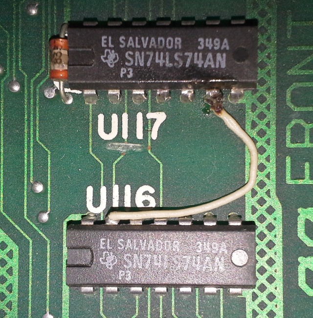
Patch cable betwween U116 and U117 moved
Moved from pin 4 of U117 to pin 6 of U117. The cut trace under the word "U117" seems to be present on stock Star Rider VGG boards.
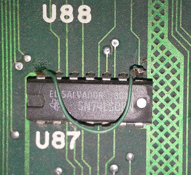
U87 mod
Pin 8 appears to have been cut off.
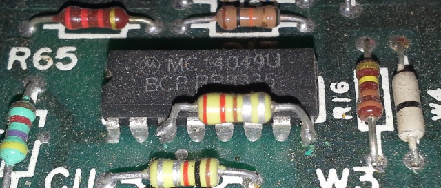
U85 (unverified) mod
I need to double check the silk screen, but I am pretty sure that this is U85. A capacitor or resistor (I am not sure which it is) has been added.
NOTE : I found this mod on a Star Rider VGG board also, so it does not seem to be Freedom Fighter specific after all.
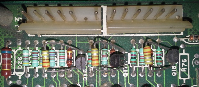
Transistor mods
Three capacitors/resistors are added to three transistors. These transistors are most likely related to the RGB monitor output circuit. My guess is that these are caps.
NOTE : I found this mod on a Star Rider VGG board also, so it does not seem to be Freedom Fighter specific after all.
U65/U84 mod
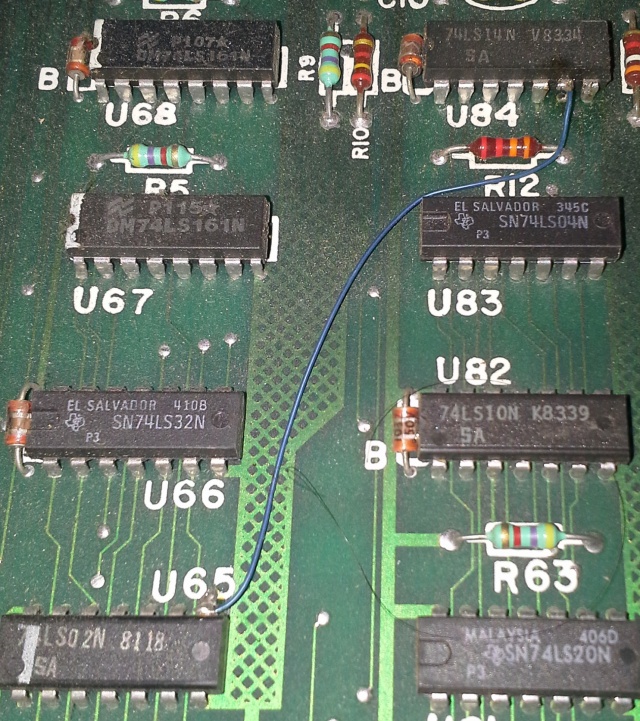
Pin 8 of U65 connected to pin 6 of U84. Part of U84 pin 6 appears to have been cut off.
U64 pin 6 is VSYNC' (DISK) on star rider VGG schematic 3/5. As the VP-931 player does not provide composite sync, the CSYNC input to the VGG board may have been replaced by something else for Freedom Fighter and thus the schematic would need to be interpreted differently.
U65 pin 8 is part of disabling the expander. If it is high, the expander is forced to be disabled.
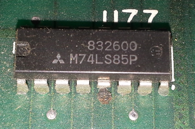
U77 mod
Pin 5 has been removed in order to prevent the expander from being disabled by the vertical line count.
PIF board
Pull-up resistor on E
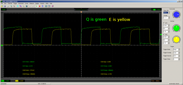
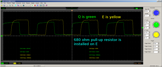
the prototype PIF board has a 680 ohm pull-up resistor on the E clock signal. I wasn't sure what effect this would have, so I tested it with my scope with and without the resistor.
The short answer is that the pull-up resistor seems to strengthen the E signal without affecting the timing.
Without the resistor:
With the resistor:
ROM program memory map
| Address Range | Description |
| 0xC000-0xFFFF | ROM (The ROM chip is a 27128 [16kB]). |
| 0xA000-0xBFFF | Doesn't appear to be connected to anything. |
| 0x8000-0x9FFF | PIA control. Similar to Star Rider, but not completely verified. |
| 0x6000-0x7FFF | Read or write to the VP-931's data lines (any address should have the same effect). Goes through a 74LS245. Writing automatically lowers WREN', while reading automatically lowers RDEN'. |
| 0x4000-0x5FFF | Doesn't appear to be connected to anything, even though the PIF ROM program does a few writes to this address at $FF82 and $FF8E (I am assuming this is a bug in the code). |
| 0x2000-0x3FFF | Read from DAV/DAK lines (any address should have the same effect). DAV will be on bit 6, DAK will be on bit 7. |
| 0x0000-0x1FFF | RAM (U2, only 2k so memory region repeats every 0-0x7FF) |
ROM Boot
Weird write commands
Freedom Fighter sends two sets of 3 byte commands to the VP-931 upon boot-up for no apparent reason. It's possibly leftover from testing/development and never removed.
ROM:FFC0 RESET:                                  ; DATA XREF: ROM:FFF0�o
ROM:FFC0                                         ; ROM:FFF2�o ...
ROM:FFC0                 lds     #$7FF
ROM:FFC4                 lda     #1
ROM:FFC6                 sta     CmdByte0        ; cmdbyte[0]
ROM:FFC8                 lda     #0
ROM:FFCA                 sta     CmdByte1        ; cmdbyte[1]
ROM:FFCC                 lda     #$FF
ROM:FFCE                 sta     CmdByte2        ; cmdbyte[2]
ROM:FFD0                 jsr     Send3CmdBytes   ; this appears to send 3 bytes to the ldp
ROM:FFD3
ROM:FFD3 loc_FFD3:                               ; CODE XREF: ROM:FFD6�j
ROM:FFD3                 jsr     sub_C257
ROM:FFD6                 bcs     loc_FFD3
ROM:FFD8                 lda     #3
ROM:FFDA                 sta     CmdByte0        ; cmdbyte[0]
ROM:FFDC                 lda     #$FF
ROM:FFDE                 sta     CmdByte1        ; cmdbyte[1]
ROM:FFE0                 lda     #3
ROM:FFE2                 sta     CmdByte2        ; cmdbyte[2]
ROM:FFE4                 jsr     Send3CmdBytes   ; this appears to send 3 bytes to the ldp
ROM:FFE7                 jsr     sub_C008
ROM:FFEA                 jmp     loc_FF80
