Eshs
From DaphneWiki
(→Video RAM Structure) |
|||
| Line 193: | Line 193: | ||
Newer EEPROMs may be fast enough. W27C512 may be a commonly available EEPROM. | Newer EEPROMs may be fast enough. W27C512 may be a commonly available EEPROM. | ||
| + | |||
| + | === Audio === | ||
| + | |||
| + | Sampled from pin 1 of the audio connector on the Esh PCB (CN1). | ||
| + | |||
| + | [[File:esh_audio_buzz.png]] | ||
Revision as of 23:02, 7 October 2020
Contents |
Esh's Aurunmilla
Memory Map
| Address Range | Description |
| 0x0000-0x1FFF | ROM H8 |
| 0x2000-0x3FFF | ROM F8 |
| 0x4000-053FFF | ROM E8 |
| 0x6000-073FFF | ROM D8 |
| 0x8000-0x9FFF | ROM C8 |
| 0xA000-0xDFFF | Not connected |
| 0xE000-0xE7FF | CPU RAM (B8) |
| 0xF000-0xF7FF | Video RAM (F3) |
Z80 Port Map
| Address Range | Direction | Description | ||||||||||||||
| 0xF0 | In | Control panel input. Only lower 6 data bits are used. Active low.
| ||||||||||||||
| 0xF1 | In | Control panel input. Only lower 6 data bits are used. Active low.
| ||||||||||||||
| 0xF2 | In | Control panel input. Only lower 6 data bits are used. | ||||||||||||||
| 0xF3 | In | Control panel input. Only lower 6 data bits are used. | ||||||||||||||
| 0xF4 | In/Out | LD-V1000 data. Writing queues a command to be sent on the next command strobe. Reading reads the most recent byte received during last the status strobe. | ||||||||||||||
| 0xF5 | Out | Misc value.
| ||||||||||||||
| 0xF8 | Out | 0 disables start 1 button lamp. 1 enables. | ||||||||||||||
| 0xF9 | Out | Start 2 button lamp. 0 disables, 1 enables. | ||||||||||||||
| 0xFA | Out | 0 disables action button lamp. 1 enables. | ||||||||||||||
| 0xFB | Out | 0 disables joystick lamp. 1 enables. | ||||||||||||||
| 0xFC | Out | Not connected | ||||||||||||||
| 0xFD | Out | Not connected | ||||||||||||||
| 0xFE | Out | 0 holds IRQ' line high (disabled) by forcing a latch to be clear. 1 stops forcing latch to be clear, which allows IRQs to set the latch. | ||||||||||||||
| 0xFF | Out | 0 holds NMI' line high (disabled) by forcing a latch to be clear. 1 stops forcing latch to be clear, which allows NMIs to set the latch. |
Z80 Interrupts
NMI: Caused by LD-V1000 status strobe going low (becoming active)
IRQ: Caused by D2 output (pin 10) on vertical PROM (C6) transitioning from 0 to 1. This ends up being 60 Hz (vsync).
Video RAM Structure
Screen is divided into 32x32 tiles. The first tile is the top left.
0xF000-0xF3FF contain which tile to show.
0xF400-0xF7FF contain tile attributes. For example, 0xF400 would have attributes about the tile index at 0xF000.
| Bit | Description |
| 0-3 | Which color palette to use for the tile. |
| 5-6 | Not used |
| 6-7 | Blink frequency. 0: no blinking, 1: blink at about 15 Hz, 2: blink at about 7.5 Hz, 3: blink at about 4.3 Hz ; The blink frequency is controlled by the Z80 program, and is not a hardware restriction. |
PROM replacements
H and V PROMs are MB7052. MB7052 may compatible with 82s129 proms, but in my tests, 82S129's overheat and fail to perform. One option is http://callanbrown.com/index.php/flep-prom-replacement-adapters
RGB PROM is MB7124. MB7124 are compatible with 82s147 proms. Haven't found any other replacement yet.
Newer EEPROMs may be fast enough. W27C512 may be a commonly available EEPROM.
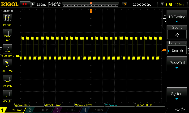
Audio
Sampled from pin 1 of the audio connector on the Esh PCB (CN1).
