FirefoxNotes
From DaphneWiki
Contents |
Firefox
Schematics
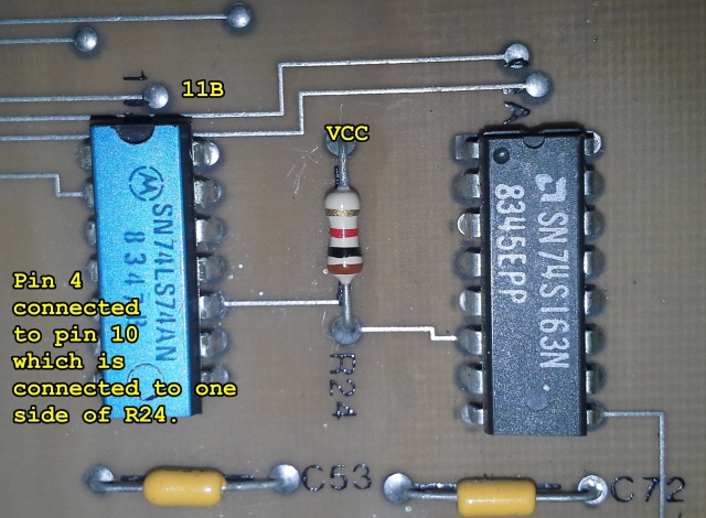
The schematics designate pull-ups with a P'RXXX type designation.
For example, on schematics sheet 9B, the monitor sync section shows 11B. Here is how it looks on the actual PCB.
Monitor
Output
Schematics show two outputs, one for a monitor supporting separate positive H and V syncs (J205B), and one for a monitor with a single negative composite sync (J205A). The pin assignments for J205B are:
| Pin | Firefox Schematic | Description |
| 1 | H | H sync |
| 2 | J | V sync |
| 3 | F | Monitor ground (aka "VID RTN") |
| 4 | E | Blue |
| 5 | C | Green |
| 6 | D | Red |
NOTE : that this is the same pins as on a G07 monitor except the pin numbering is reversed (ie on the G07, pin 1 is red).
If you use composite sync, and it doesn't appear to sync properly, then make sure R240 (1k ohm) is installed on the Demodulator PCB. (from DLP archives)
Sync signals
Sniffed from real hardware (although I was still having sync problems, so this may not be correct. It looks right to me, however).
Distance between start of vsync was measured at 16.683, so it seems correct.
Sync problems
Check/replace U6 (74LS04) on the Demodulator PCB.
Slow speech problems
> The PCB generated speech is very slow, like Jim Carrey doing his Slo-Mo act..
Make sure R101 is set correctly on the Demodulator PCB. Refer to the manual for setting the PLL Lock signal (I think the manual covers it). Use a frequency counter and make sure you measure stable 3.58MHz at TP22 and 14.318MHz on R230 (either end of it).
If you correct the sync problem and the speech is still slow then the cause is likely further down the circuit where the 14.318MHz is divided to 7.12MHz (on the Graphics PCB) before then going to the Main PCB.
Check the frequency on pin 2 of 3M (74LS163) on the Main PCB. You should measure 7.12MHz of at least 3Vpp. If not then follow the signal back to the GFX PCB then the Demodulator PCB (make sure the PLL is set correctly before doing anything).
If there is 7.12MHz on pin 2 of 3M then check the inverter/driver between pin 12 of 3M and the TMS5220 (pin 6 of 3H).

