FirefoxNotes
From DaphneWiki
(→Laserdisc Interface) |
(→Laserdisc Interface) |
||
| Line 96: | Line 96: | ||
Data is loaded (from DBB0-DBB7) into an LS374 via DSKLATCH'. It is then output via WRDSK' (which is tied to WREN'). '''Presumably, this means that WREN' may go low slightly before the data is valid (and being written to the bus) and may go high slightly before the data is invalid.''' | Data is loaded (from DBB0-DBB7) into an LS374 via DSKLATCH'. It is then output via WRDSK' (which is tied to WREN'). '''Presumably, this means that WREN' may go low slightly before the data is valid (and being written to the bus) and may go high slightly before the data is invalid.''' | ||
| + | |||
| + | === ROM/RAM diagnostic test === | ||
| + | |||
| + | The ROM/RAM test will hold WREN' low which is of interest for Dexter development. | ||
Revision as of 18:03, 3 April 2015
Contents |
Firefox
Schematics
The schematics designate pull-ups with a P'RXXX type designation.
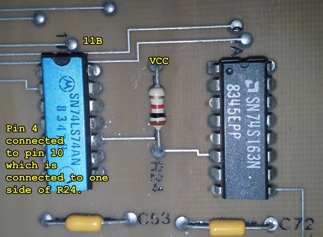
For example, on schematics sheet 9B, the monitor sync section shows 11B. Here is how it looks on the actual PCB.
Monitor
Output
Schematics show two outputs, one for a monitor supporting separate positive H and V syncs (J205B), and one for a monitor with a single negative composite sync (J205A). The pin assignments for J205B are:
| Pin | Firefox Schematic | Description |
| 1 | H | H sync |
| 2 | J | V sync |
| 3 | F | Monitor ground (aka "VID RTN") |
| 4 | E | Blue |
| 5 | C | Green |
| 6 | D | Red |
NOTE : that this is the same pins as on a G07 monitor except the pin numbering is reversed (ie on the G07, pin 1 is red).
If you use composite sync, and it doesn't appear to sync properly, then make sure R240 (1k ohm) is installed on the Demodulator PCB. (from DLP archives)
Sync signals
Sniffed from real hardware (although I was still having sync problems, so this may not be correct. It looks right to me, however).
Distance between start of vsync was measured at 16.683, so it seems correct.
Sync problems
Check/replace U6 (74LS04) on the Demodulator PCB.
Slow speech problems
> The PCB generated speech is very slow, like Jim Carrey doing his Slo-Mo act..
Make sure R101 is set correctly on the Demodulator PCB. Refer to the manual for setting the PLL Lock signal (I think the manual covers it). Use a frequency counter and make sure you measure stable 3.58MHz at TP22 and 14.318MHz on R230 (either end of it).
If you correct the sync problem and the speech is still slow then the cause is likely further down the circuit where the 14.318MHz is divided to 7.12MHz (on the Graphics PCB) before then going to the Main PCB.
Check the frequency on pin 2 of 3M (74LS163) on the Main PCB. You should measure 7.12MHz of at least 3Vpp. If not then follow the signal back to the GFX PCB then the Demodulator PCB (make sure the PLL is set correctly before doing anything).
If there is 7.12MHz on pin 2 of 3M then check the inverter/driver between pin 12 of 3M and the TMS5220 (pin 6 of 3H).
Laserdisc Interface
Data lines
All of the data lines have 220 ohm pull-ups and 330 ohm pull down resistors on them (on the firefox main PCB).
Reading from VP931
RDDSK' is tied to RDEN' via an LS244.
Reads are handled by an LS244 which becomes active when DREAD' goes low (and feeds into the DBA0-DBA7 data lines). DREAD' is the clock (pin 11) input for an LS74 (7H on the schematic). Clear' (pin 13) is held permanently high by a pull-up. Set' (pin 10) is tied to DSKREAD'. Q' (pin 8) is tied to RDDSK'.
DSKREAD' is 0x4218-1F (set up for disk read, write strobe for set up) DREAD' is 0x4105 (read status data from disc)
The process to read (from the ROM's perspective is):
- Write anything to DSKREAD' which causes RDDSK'/RDEN' to go low. (no read actually occurs at this point)
- Read from DREAD' which causes the LS244 to become active and send the VP931's data lines through to DBA0-DBA7. CPU will begin reading the bus while DREAD' is active, which is somewhere in the middle of the RDEN' pulse.
- Once the CPU's address lines change (by transitioning to the next CPU instruction), DREAD' will go high which will trigger the clock of the LS74 (7H, pin 11), which causes RDEN' to go high because the input to the flip flop is ground. The bus data needs to stay readable for 10ns after the CPU address changes (according to 6809E datasheet).
Writing to VP931
WRDSK' is tied to WREN' via an LS244.
Data is loaded (from DBB0-DBB7) into an LS374 via DSKLATCH'. It is then output via WRDSK' (which is tied to WREN'). Presumably, this means that WREN' may go low slightly before the data is valid (and being written to the bus) and may go high slightly before the data is invalid.
ROM/RAM diagnostic test
The ROM/RAM test will hold WREN' low which is of interest for Dexter development.

