FreedomFighterNotes
From DaphneWiki
(→U65/U84 mod) |
(→U85 (unverified) mod) |
||
| Line 13: | Line 13: | ||
=== U85 (unverified) mod === | === U85 (unverified) mod === | ||
I need to double check the silk screen, but I am pretty sure that this is U85. A capacitor or resistor (I am not sure which it is) has been added. | I need to double check the silk screen, but I am pretty sure that this is U85. A capacitor or resistor (I am not sure which it is) has been added. | ||
| + | |||
| + | '''NOTE : I found this mod on a Star Rider VGG board also, so it does not seem to be Freedom Fighter specific after all.''' | ||
[[File:FFR_U85_CapResistor_Mod2.jpg|640px]] | [[File:FFR_U85_CapResistor_Mod2.jpg|640px]] | ||
| + | |||
=== Transistor mods === | === Transistor mods === | ||
Three capacitors/resistors are added to three transistors. These transistors are most likely related to the RGB monitor output circuit. My guess is that these are caps. | Three capacitors/resistors are added to three transistors. These transistors are most likely related to the RGB monitor output circuit. My guess is that these are caps. | ||
Revision as of 16:13, 13 March 2015
Contents |
Prototype
Difference in Freedom Fighter VGG board from Star Rider
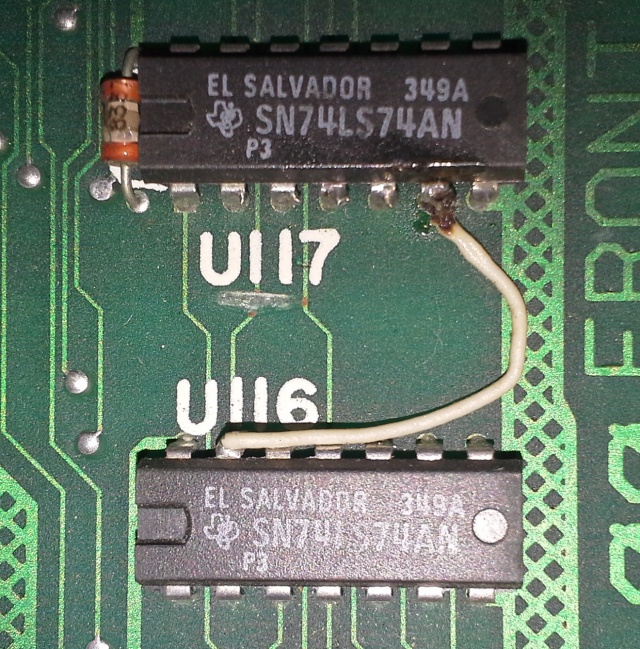
Patch cable betwween U116 and U117 moved
Moved from pin 4 of U117 to pin 6 of U117. The cut trace under the word "U117" seems to be present on stock Star Rider VGG boards.
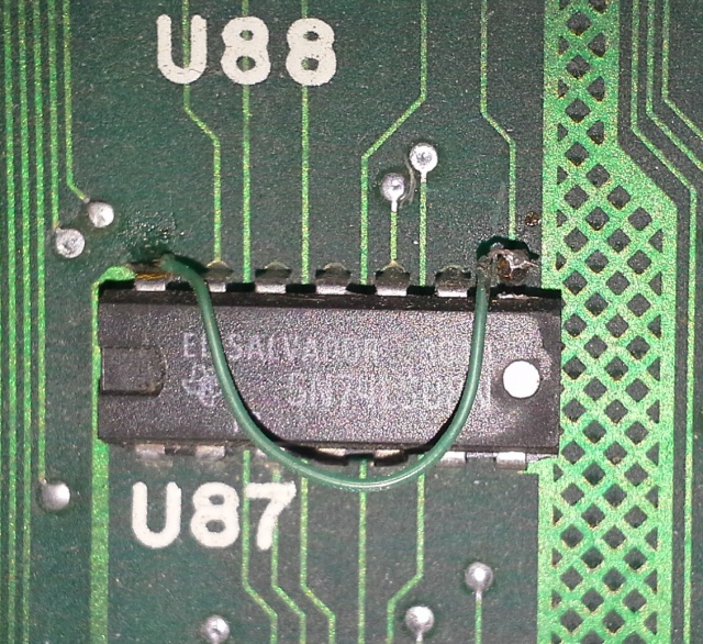
U87 mod
Pin 8 appears to have been cut off.
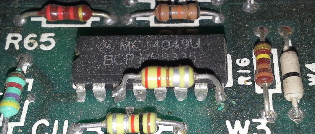
U85 (unverified) mod
I need to double check the silk screen, but I am pretty sure that this is U85. A capacitor or resistor (I am not sure which it is) has been added.
NOTE : I found this mod on a Star Rider VGG board also, so it does not seem to be Freedom Fighter specific after all.
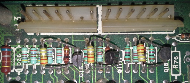
Transistor mods
Three capacitors/resistors are added to three transistors. These transistors are most likely related to the RGB monitor output circuit. My guess is that these are caps.
U65/U84 mod
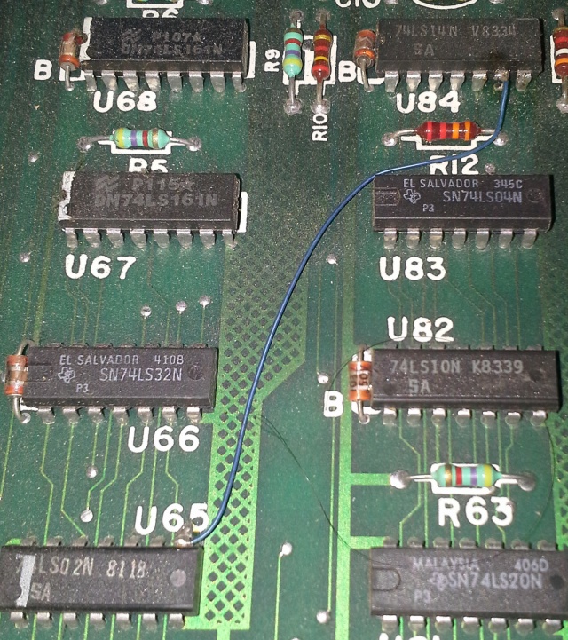
Pin 8 of U65 connected to pin 6 of U84. Part of U84 pin 6 appears to have been cut off.
U64 pin 6 is VSYNC' (DISK) on star rider VGG schematic 3/5. As the VP-931 player does not provide composite sync, the CSYNC input to VCC may have been replaced by something else for Freedom Fighter and thus the schematic would need to be interpreted differently.
U65 pin 8 is part of disabling the expander. If it is high, the expander is forced to be disabled.
U77 mod
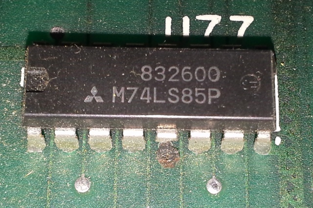
Pin 5 has been removed in order to prevent the expander from being disabled by the vertical line count.
